Rackmounting a Triax Quad Channel Modulator
Preamble
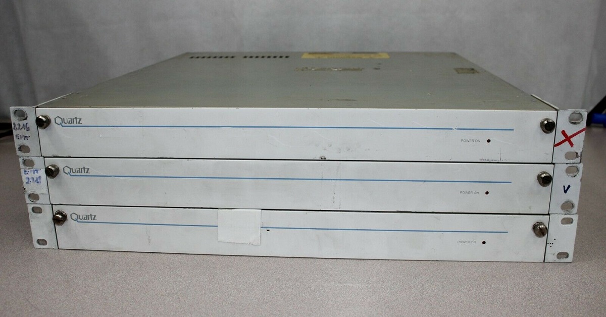
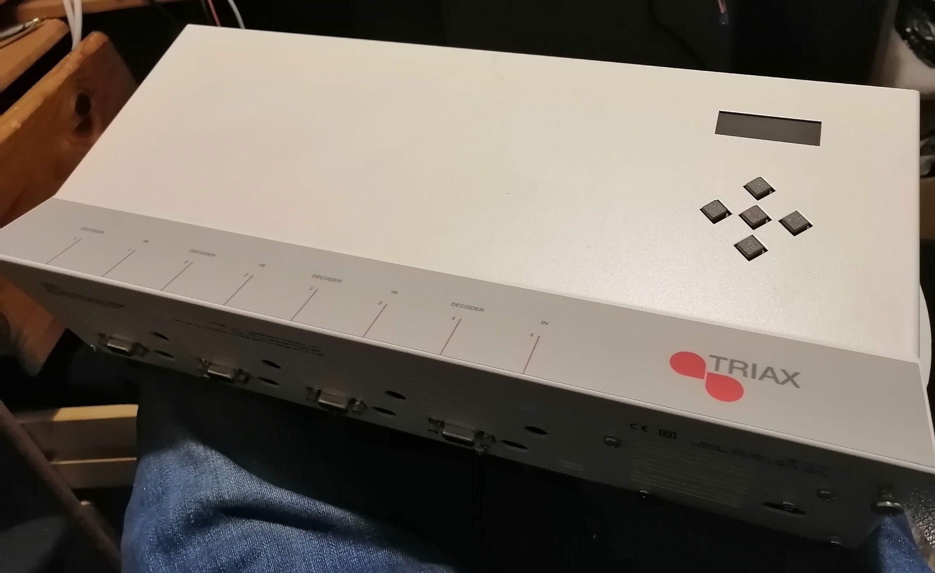
While browsing eBay back in 2021, I came across this Triax CM04U Quad Channel TV modulator. What piqued my interest was the low price of only £22 - and also the internal images which appeared to show a selector for "mono" or "stereo".
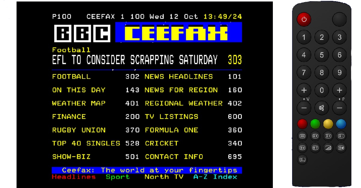
In case you aren't familiar, standard analogue TV has a single, mono, FM subcarrier for the audio. To get stereo sound, here in the UK we used something called "NICAM", which adds a digital subcarrier beside the FM one to give an additional two channels of high quality audio. Since that's not straightforward to generate, very few modulators do NICAM, even those with stereo inputs - these are almost universally summed internally.
With this in mind, you might begin to realise why seeing a modulator with "Stereo" marked on the PCB was interesting to me. I didn't think there was much chance of it actually generating it's own NICAM signal, but it may at least have a "2nd IF" input that I could inject my own into - should I ever manage to obtain a NICAM coder.
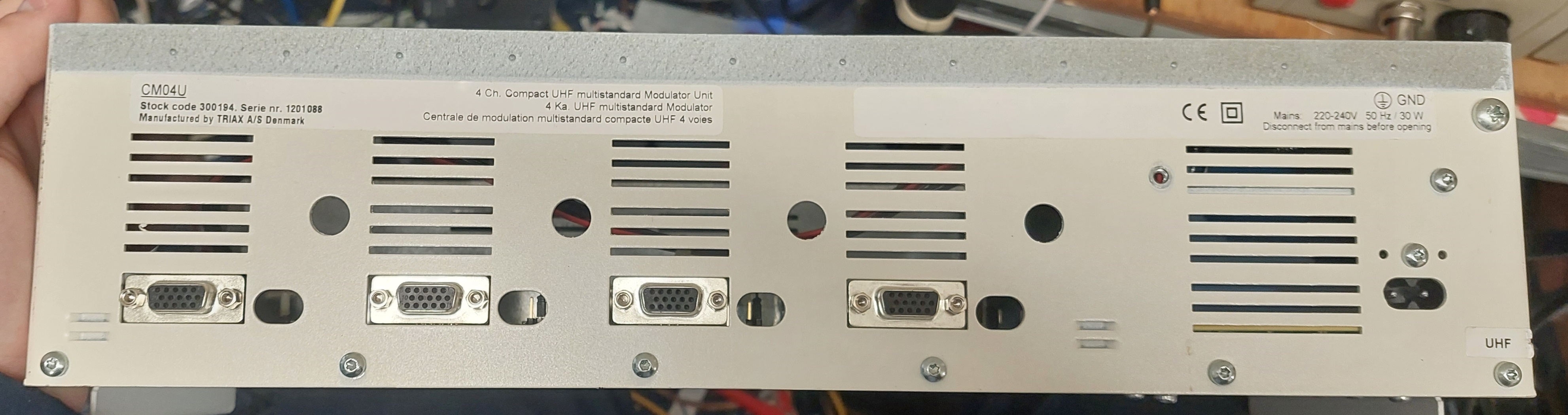
Anyway, the modulator has a few other idiosyncrasies - for a start, it uses a 15 pin, high-density D-type connector for each channel's input. This is a huge pain - it means you need to make up 4 conversion leads - and hi-density d-types are particularly horrid to terminate.
The other weird thing was the amount of space inside, coupled with additional connector holes on the case, and an internal header for each channel block. I began to wonder if it was possible to get a satellite receiver card or some other codec which mounted inside to make a self-contained cable-TV headend for a Hotel or similar. As yet I haven't found any info to back this up.
Rackmounting
Since most of my TV equipment is mounted in a 19" rack in the attic, I decided that I could kill two birds with one stone by transplanting the modulator into a rack-mountable case. This would also give me loads of space to mount some sensible audio, video and NICAM input connectors on the rear.
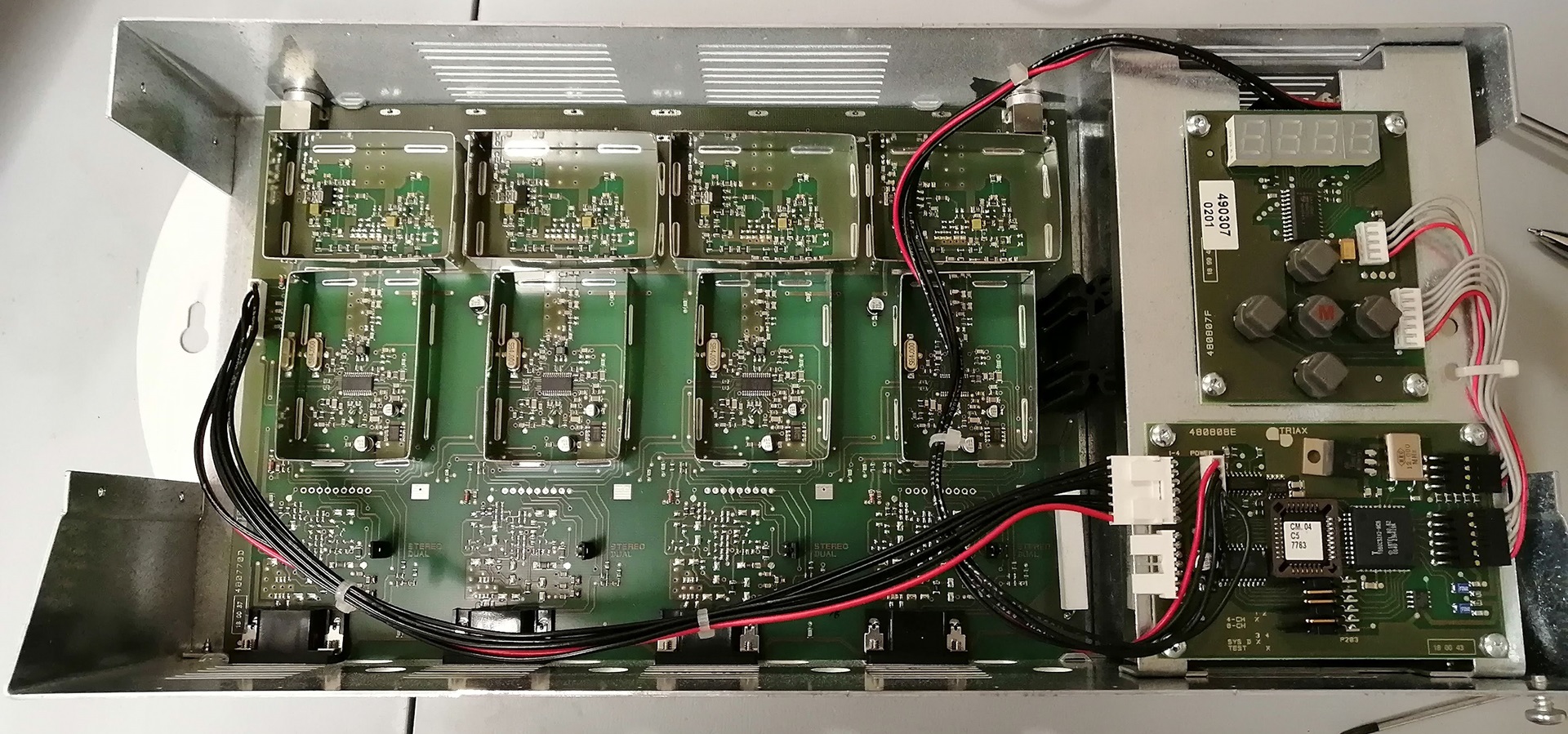
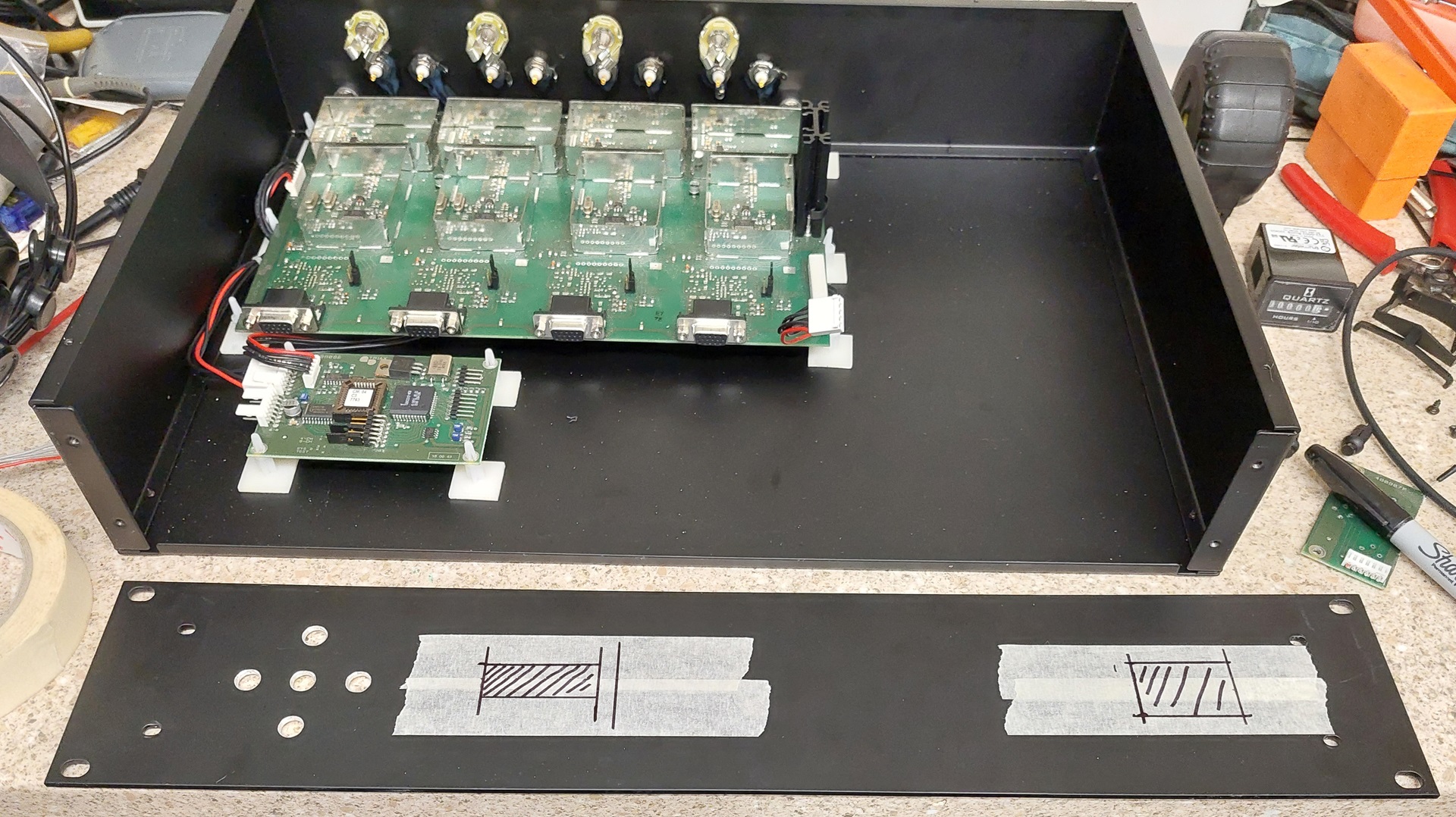
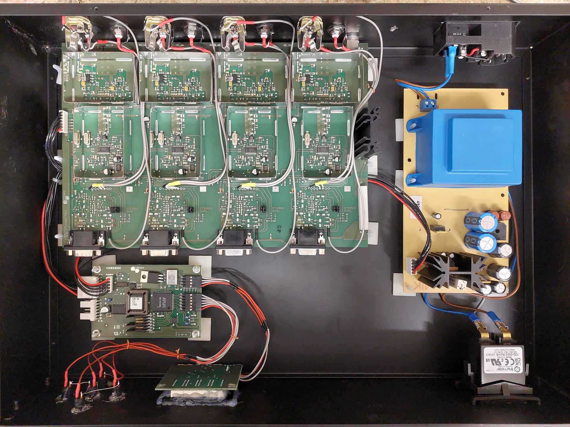
To this end, I measured up the modulator's componenets and selected a black, 2U, metal case from CPC. I then stripped everything out of the existing case and began lining things up to see how this would go together.
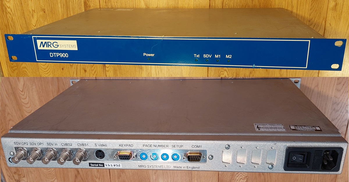
At this point, the first snag became apparent: the main board had been held in place by grooves in the case, and there were no mounting holes at all. Fortunately, I'd recently been taking apart from equipment from MRG systems and noticed a little trick they used.
This came in the form of self-adhesive PCB stand-offs; Turns out they will work just as well with the lug pushed up against the edge of a PCB, provided of course you have enough of them on all sides to lock it in place and prevent sliding around.
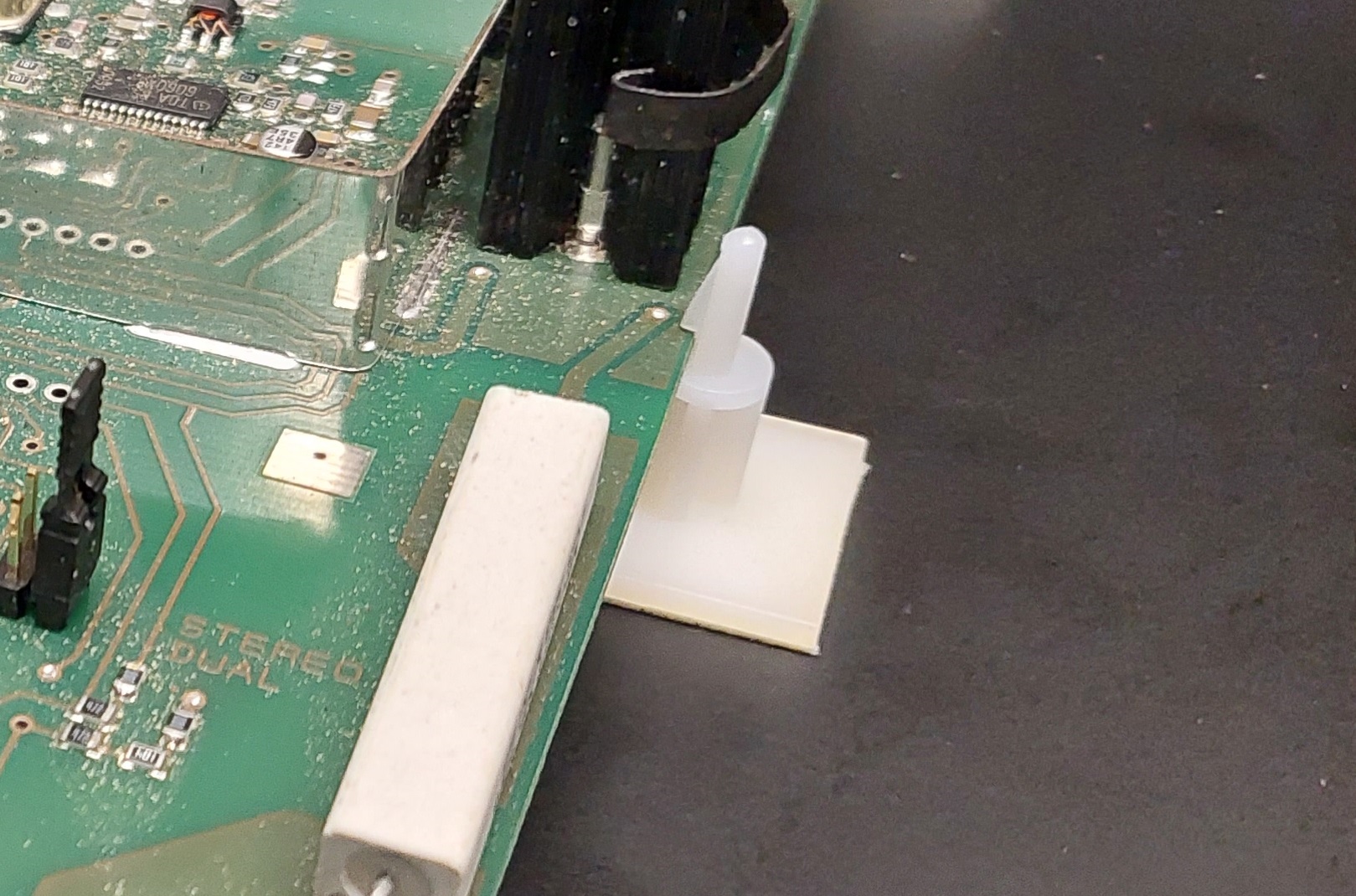
The other potential blessing of this solution was the sheer ease of mounting everything in the right place. Normally this would involve lots of careful measurements - all one drill wobble away from not fitting properly. With the self-adhesive mounts I could literally clip them in and carefully set the board where I wanted it, and job done!
I've always been very skepticle about self-adhesive mounting solutions - I find they rarely live up to expectations. I figured I'd give it a try - and if they didn't hold, a dab of epoxy, or perhaps even a screw drilled up through the base, would solve the issue. Fortunately though this hasn't been an issue so far.
Rear panel connectors
Now I knew how I was mounting the boards, I got the main board lined up and marked on the rear panel where the cutouts for the two F-connectors need to go.
These are the only connectors on the PCB that I'm directly bringing out the rear panel - everything else will be brought back via flying leads internally. All the same, it was important to get these holes just right, as the connectors also formed a useful mechanical mount.
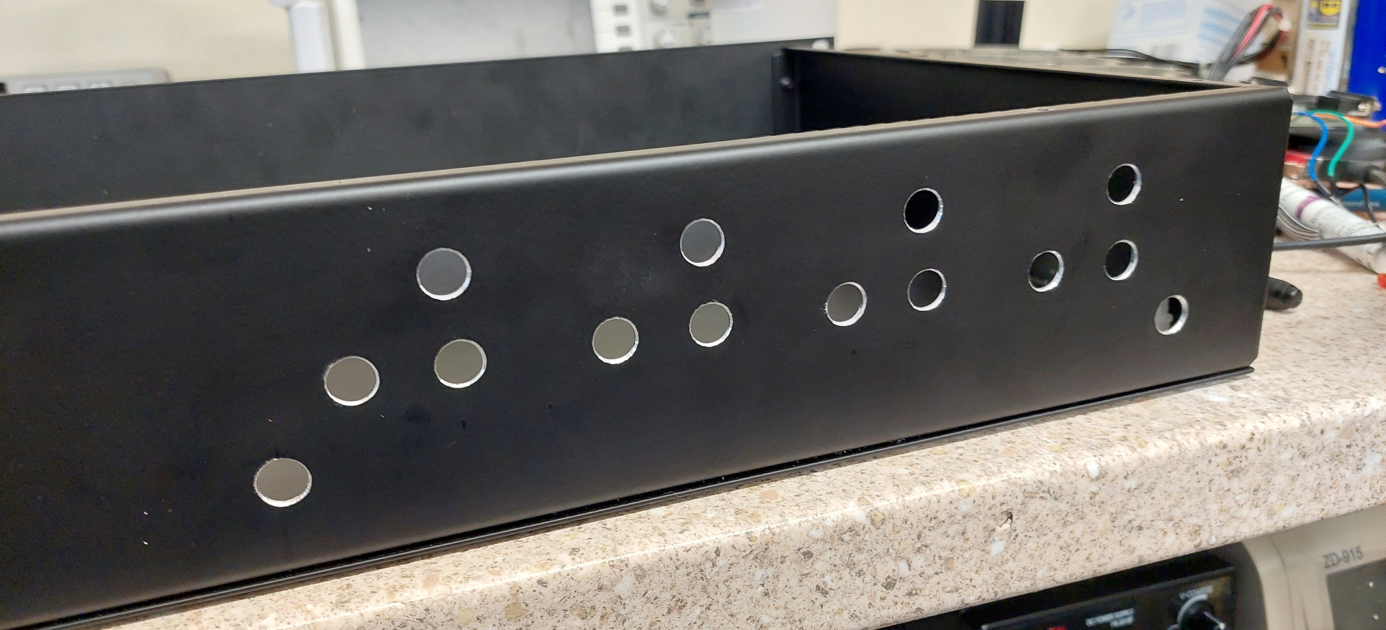
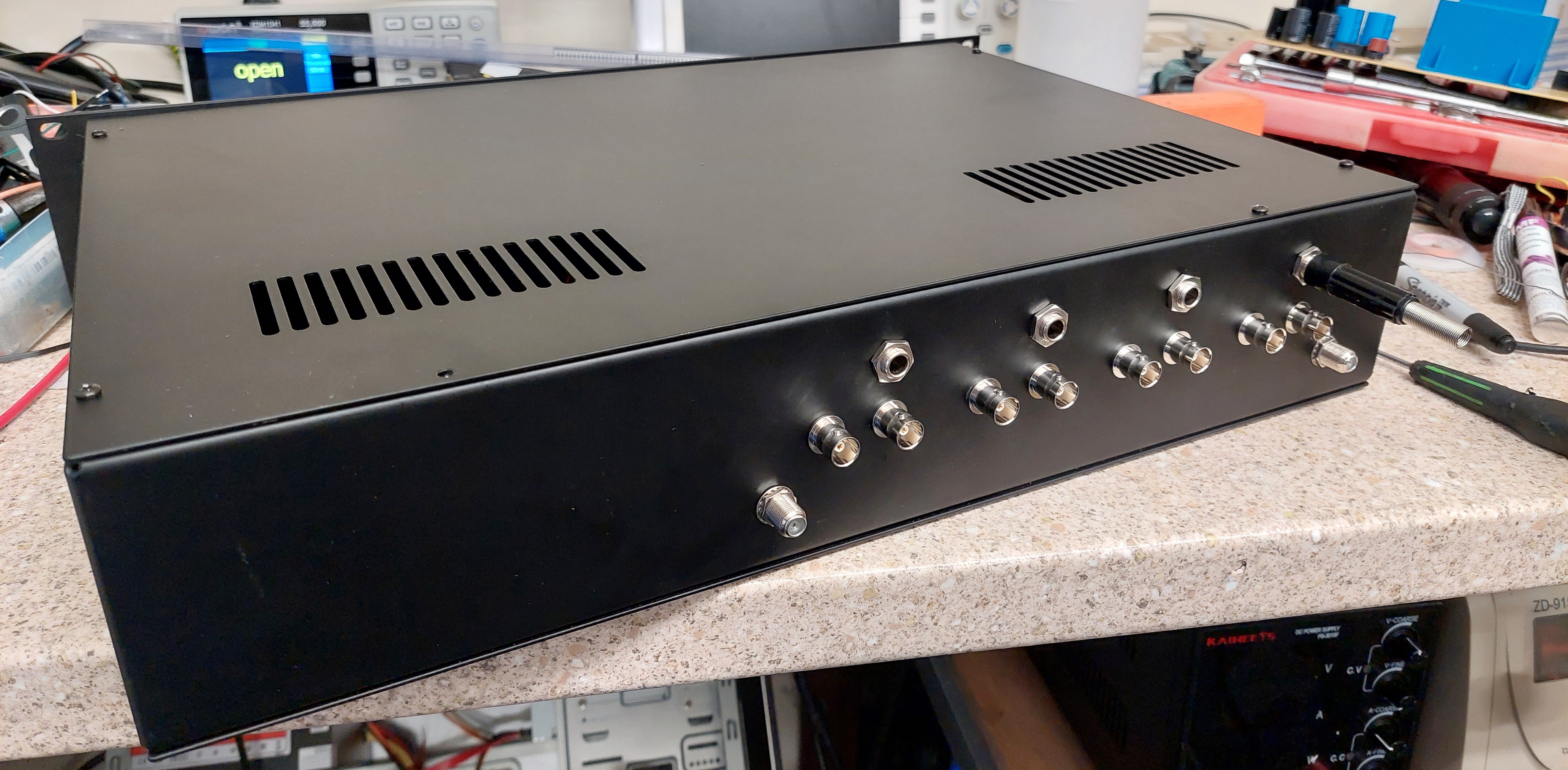
With those holes made, I used them as a reference to mark out where all my other connectors needed to go. Each channel would need three connectors - two BNCs for the Video and NICAM inputs, and an A gauge jack for the mono FM input.
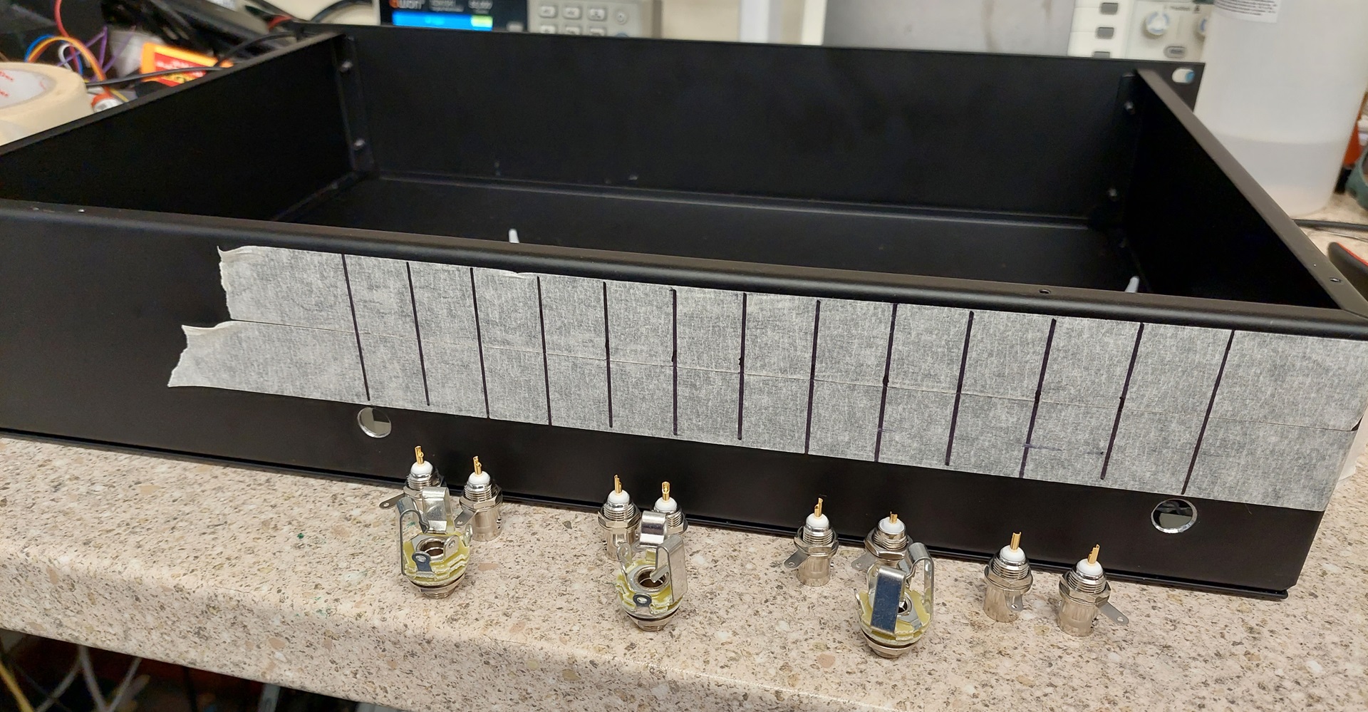
To make sure these came out looking professional, I covered the rear panel with masking tape and marked it in a grid pattern. I then used a centre punch to mark where each of the twelve connecters needed to go. These were then started with a pilot hole, and enlarged with a stepped drill bit. I was very pleased with how the finished panel turned out.
Front panel
With the connectors all mounted, but not wired yet, I turned my attention to the front panel. Now, in the early stages of this project I had various grand ideas to replace the front panel and microcontroller - but when "push came to shove" I decided that it would be much easier to just use the existing board, with a few modifications.
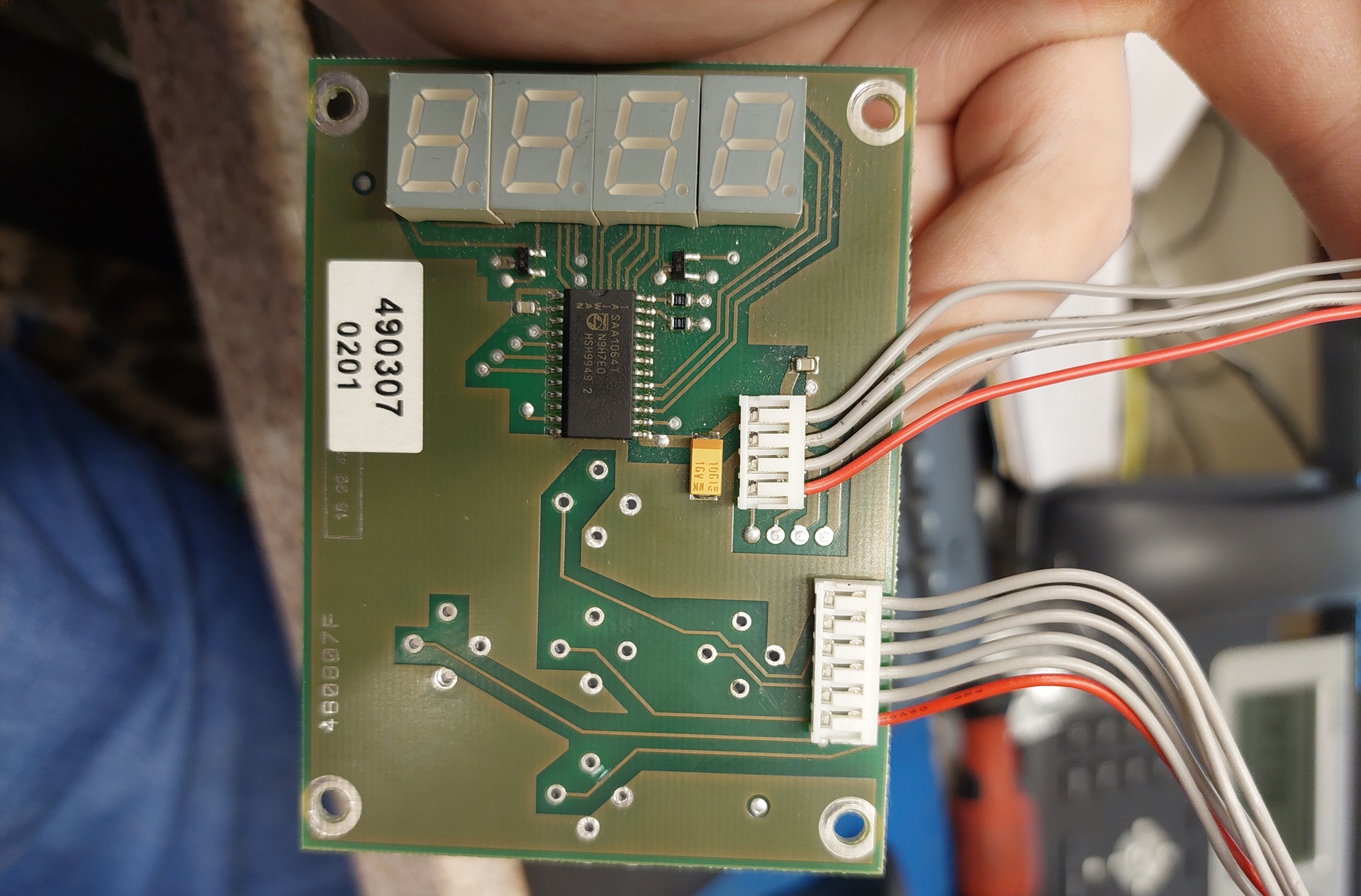
I started off by picking a good spot in the case for the controller board - fortunately there was loads of space left in the front, but the problem was the leads between this board and the LED display were much too short, and would need to be extended. Oh well, can't have everything, eh?
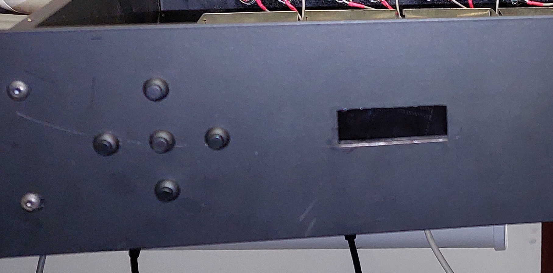
Next problem was that the LED display originally had the arrow keys mounted below it, like "portrait" orientation. This meant that it was actually too tall to fit on the front panel! Fortunately, since I was intending to make my own controls on the front panel anyway, the solution was to simply cut that section of the PCB off. Not especially proud of that move, but I got away with it - and the alternative would likely have involved completely re-building that section.
Speaking of things I'm "not especially proud" of - whilst this board did at least have mounting holes, they were too close to the LEDs for the self-adhesive mounting brackets to work - and would have been too long anyway, leaving the screen too far from the front. I knew that, given my lack of fabrication skill, the chances of making a neat mounting solution involving drilling through the front panel were pretty slim - so instead I opted to simply hot glue the entire board to the metal case. Yeah, really not proud of that one - but again, it got the job done!
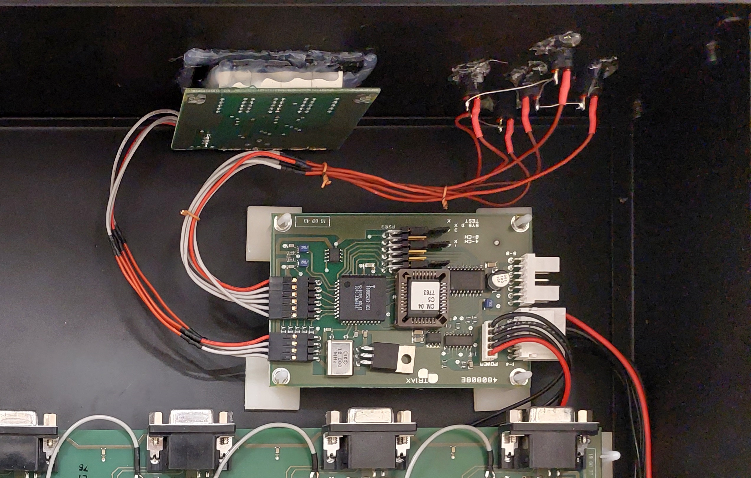
I decided to fashion the keypad from individual, small, pushbuttons. They were then wired up to match the original PCB layout. This worked flawlessly - they even line up pretty well, which when I'm on the end of a drill is always something of a gamble.
Finishing Touches
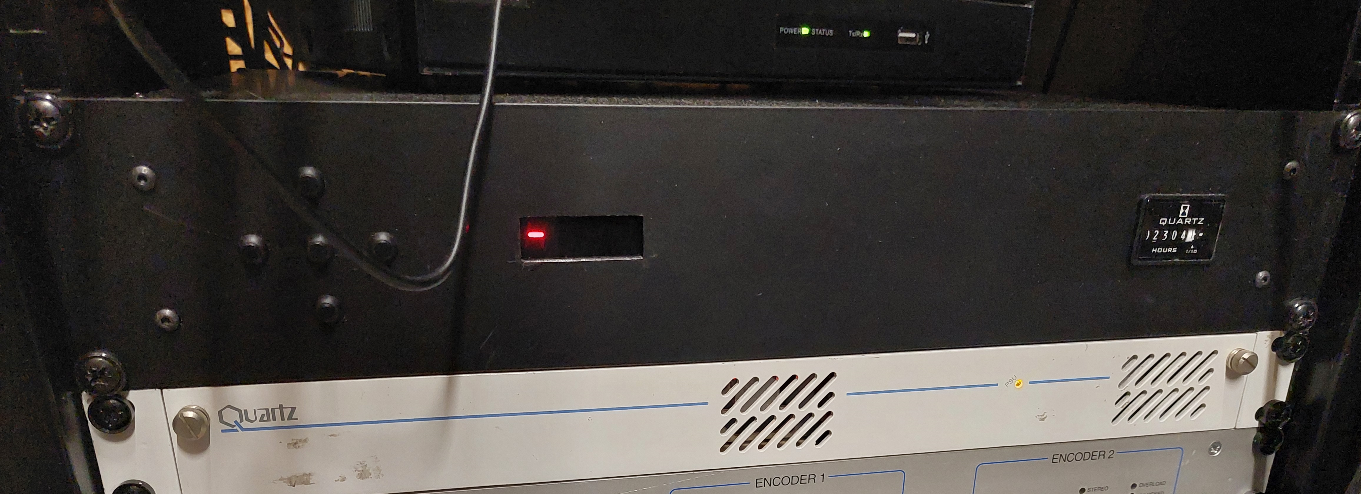
With the hardest parts done, there were only a few things to finish up. Firstly, I needed to mount the PSU board, as well as a rear inlet socket, and an hour counter. The hour counter was something of an afterthought - and more or less entirely because the last transmitter I built has one too... Anyway, the hardest part of this was cutting out rectangular holes for the socket and counter.
Lastly, I wired up all the rear connectors. Now, strictly speaking one should use proper 75 ohm coaxial cable for this - but the only stuff I had lying around was the full-on TV aerial style coax, which isn't exactly suited to soldering directly onto PCB traces. So instead, I used some shielded audio cable for everything.
To prove this wouldn't have a detrimal effect on any video signals, I cut a length of cable several meters long, terminated it with a 75 ohm resistor, and injected it with sine waves from a function generator. Even with the generator cranked up to it's max output of 60MHz, the cable barely dropped a couple of mV - so I'm happy that a few CM of this cable inside isn't going to completely ruin the analogue video. I've seen similar cable used in broadcasting equipment for HD-SDI signals with no problems either...
At this point, I got the completed unit fitted into the rack upstairs, and applied a few signals. Fortunately the unit seems to have survived it's transplant admirably, and still kicks out it's four channels at such a level I ended up putting a 20dB attenuator on the RF output to quieten it down a bit!
- Nathan Dane, June 2024