Subrack Power Supplies
The design brief behind these power supplies was pretty simple.
- Provide three rails, +5v, +15v and -15v to allow future use with audio and other analogue signal amplifiers/processors etc. These generally require voltages on both sides of ground, and building negative circuits into each one would be pretty inconvenient and inefficient.
- Allow multiple power supplies to be paralleled together for redundancy and/or increased power.
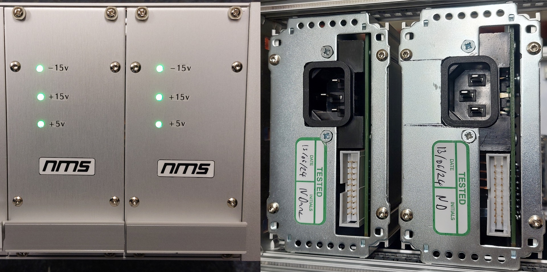
- Provide clear indication of the supply status from the front panel.
- Use a connection interface that allows for subrack modules to be easily added or removed without interfering with power to adjacent units.
- Power via an industry standard C13 plug
- Use well tested, highly available, but low cost, off-the-shelf hardware where possible.
I decided that the best way to meet all these requirements was to design a carrier board - this would hold all the connectors, an industry standard 5"x3" power supply, and some front panel indicator LEDs.
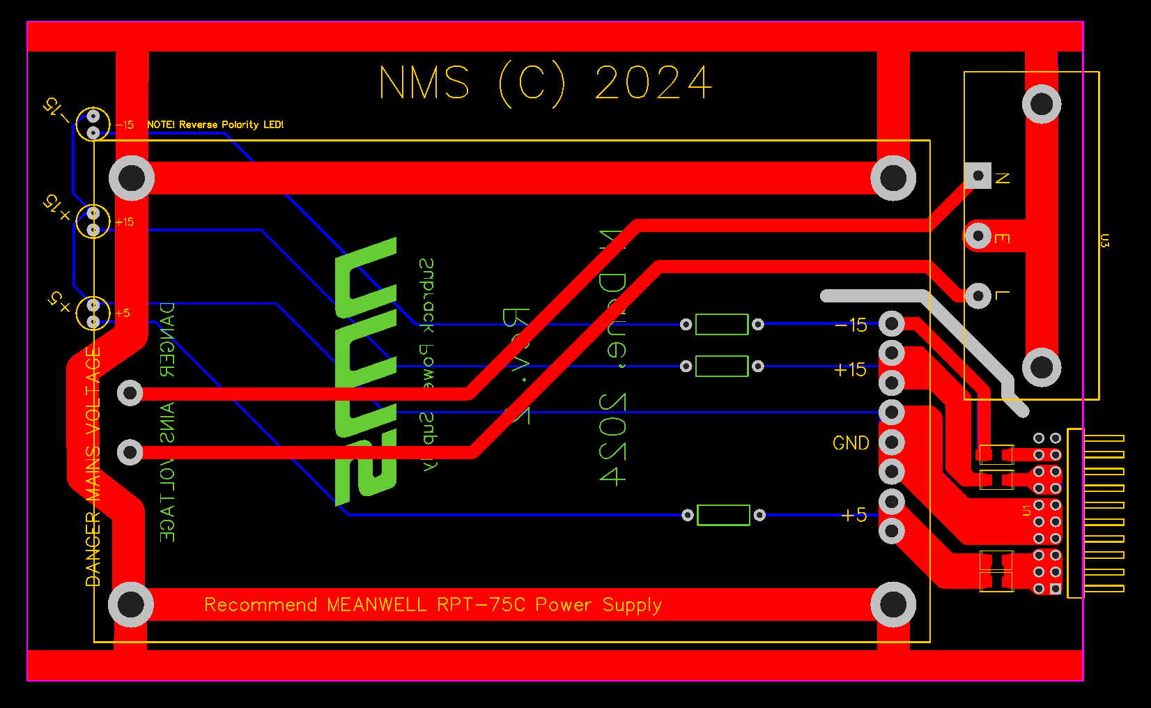
The PCB was designed to keep the mains as well seperated from the DC output as possible - where they came in close proximity near the rear connectors I added an anti-tracking slot, for extra assurance.
I also added a grounding trace, this connects to all the 'pillers' which hold the PSU module, and also to two strips along the edges intended to provide good ground contact to te rest of the chassis.
Thick traces connect the PSU's DC output to several Schottky diodes connected in parallel, and then on to the rear connector.
The whole PCB is designed to be made with the thicker 2g/oz copper traces, just to make things as efficient as possible.
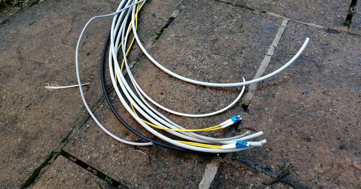
The idea here is to use a ribbon cable along the rear of the subrack, essentially forming a power 'bus' (along with two spare conductors for future data transfer). Cards, and indeed the power supplies, can be moved or replaced without the need to completely de-power or re-wire the entire subrack.
Tapped off from the PSU module's output, before the Shottky diodes, are the indicator LEDs. This assures that even when multiple power supplies are connected in series the indicator lights will only light when that specific PSU is working properly - as the diodes prevent any back-flow from the bus.
For the PSU module, I decided to use Meanwell RPT-75C units. They are widely available from RS Components, and I know Meanwell supplies to be reliable.
In this case, the module is designed to be mounted face-down on the carrier PCB.
First, the output connectors must be removed, and ideally the adjustment trimpot should be removed and placed on the opposite side of the PCB - this will leave it much more accessible in future.
The module is then physically connected to the carrier board via 4, 30mm M4 stand-offs and screws.
This also ensures a good ground connection is made to the PSU module.
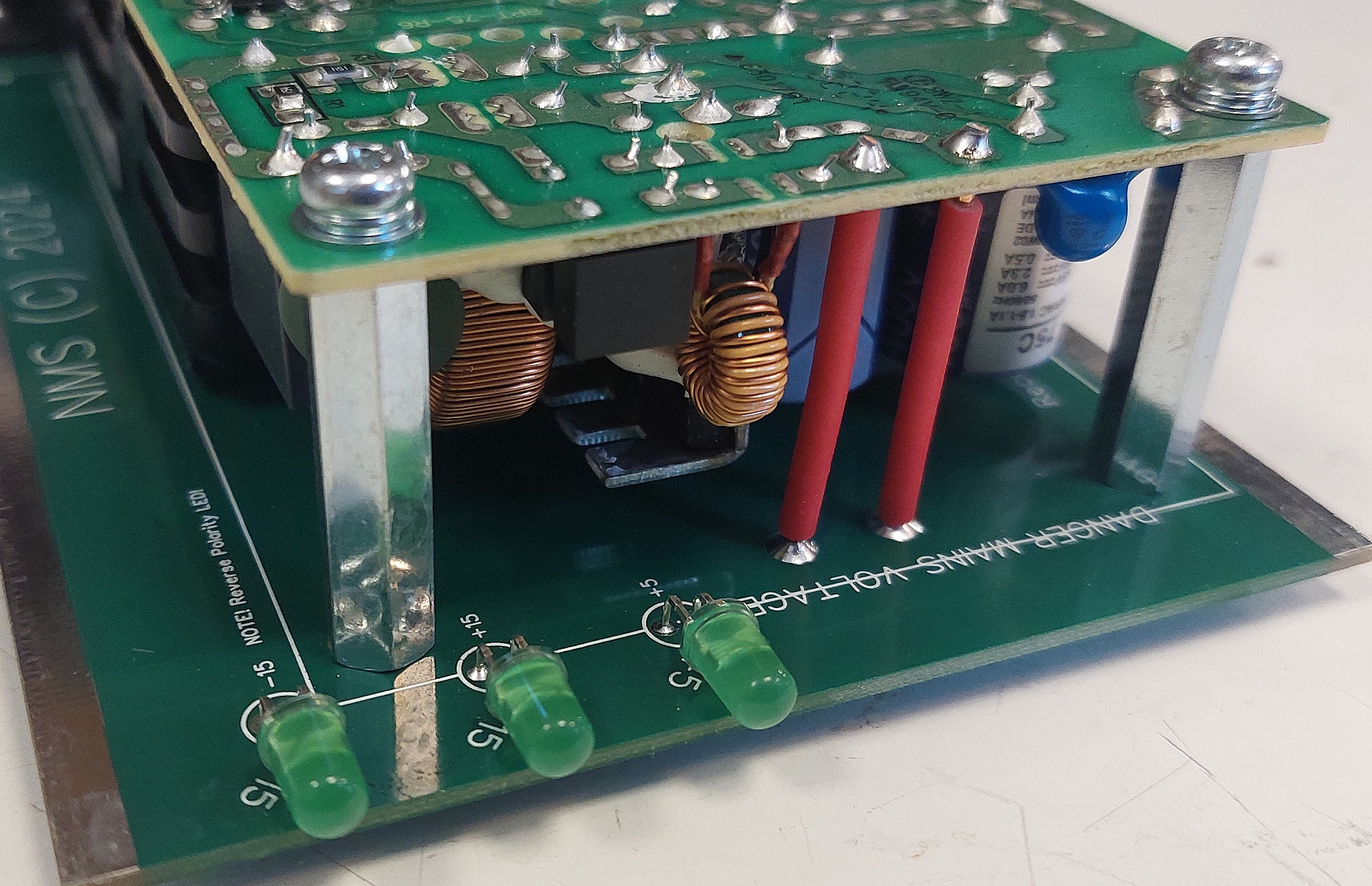
Next, I used stiff copper wire (stripped mains T&E) to connect the PSU module to the carrier board electrically. I did add some sleeving to the mains wires, but the DC connections are bare.
The resistors for the front panel LEDs are soldered to the rear of the carrier board - this is to give plenty of clearance from the PSU's heatsinks. Something to note here is that you have three modern high brighness LEDs all powered from different rails - to get them looking even I just toyed with different values of resistors until they were both not too bright, and of even brightness.
The result is seriously underdriven LEDs - these will likely well outlast the PSU module - even though they still appear brighter than your standard LED.
To ensure the units were safe, I decided to do an old-style earth continuity test that isn't really standard practice any more.
To this end, I clipped a bench power supply to the C13 earth pin and the PSU chassis, and turned it up to it's maximum current of 10 amps.
This was no problem to the earthing arrangement, and revealed a very low impedance of less than an ohm. This gives me assurance that any problems will at least not result in the metal case coming alive!
I also tested the units with a more conventional automatic PAT tester, which also passed with no problems.
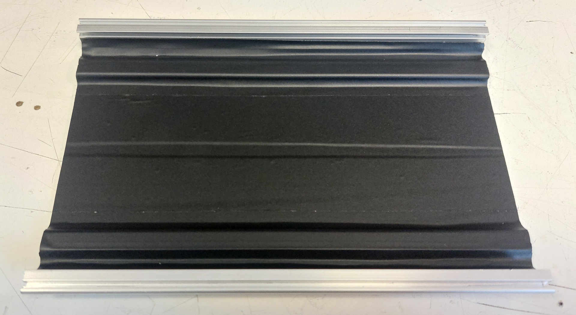
Speaking of the chassis, I decided to line the internals with vinyl - this just gives one more layer of protection from the mains. I really don't think that was required at all, but it gives additional peace of mind.
The front panel is very simple, it only needs three 3mm holes for the LEDs to shine out through. These were then labelled up with my usual trimmed Brother P-Touch labels to make it clear which rail the indicator is for.
The holes were then stopped with 3mm "light pipes" from RS. These are amazing little things, brilliant for hiding the fact that your holes were drilled slightly off-centre - and you can 'adjust' the LEDs behind to find the optimal spot.
One thing to note, though - the cases I used are designed to have covers on the top and bottom. I have removed these to allow easy heat convection through the units.
This will obviously be fine once they're buried in a rack, but when out on a bench for testing you can easily reach inside and contact live parts! Therefore I would suggest that whilst they're 'safe', they aren't 'idiot proof'!
I should really replace those covers with their mesh equivilants - although to be honest, I can't see there being a huge amount of heat anyway - the standard covers would likely work fine.
This is something to report back on once they've been under heavy load in a hot attic for a few hours, I think!
Parts List
| Name | Part | Link | Price* |
|---|---|---|---|
| Case | 12HP, 3U, 160mm case from Nvent Schroff | Nvent Schroff #24813-412, available on eBay | £12 |
| Power Supply Module | Meanwell RPT-75C | RS 020-0011 | £36.63 |
| Mains Connector | Bulgin PX0580/PC | RS 487-261 | £3.13 |
| DC Connector | 20 way, 2.54mm - AWHW 20A-0202-T | RS 674-1264 | £0.92 |
| Light Pipe | 3mm - Bivar PLP2-100 | RS 174-9771 | £1.86 |
| Schottky Diodes | 3A - B340A-13-F | RS 738-4778 | £2.64 |
| Stand-offs | 30mm M4 - 971100471 | RS 176-8316 | £1.56 |
| Screws | M4 with spring & flat washer | RS 693-4827 | £0.15 |
| TOTAL | £58.89 |
*prices are for the number of components required to build ONE unit, and were correct at time of writing. No attempt has been made to adjust for bulk discounts, acts of God (hail, floods, plague), etc.
Click here to download the PCB Gerber files
- N Dane, August 2024