DIY Router/Gateway with built-in UPS
When I (finally) got fibre-to-the-premises at the start of 2022, I wanted to make a big upgrade to my home network. This [will be] covered elsewhere - right now, let's have a look at the rackmount router I built.
While I generally refer to it as a "router" or "gateway", truth is it's so much more than that. It runs Nginx to proxy traffic back for my various websites to the appropriate server, FreePBX for my home phone system, as well as DNS, DHCP and a Wireguard VPN.
That's mainly why I decided to install "raw" Linux Debian rather than some network-specific distro like pfSense or openWRT - doing it this way lets me treat it the same as any other server, just makes the actual networking bit slightly more involved.
Anyway, preamble out of the way, let's take a look at what I bought:

Like any good electronics geek, first thing I did on receiving the unit from Aliexpress was to take it apart. Just as well I did too - that blue lead was hanging out!
You can see it's a very simple device. We have essentially an SBC with lots of network ports, connected to a nice MeanWell power supply. There's also a VGA port on the rear panel connected via a long ribbon cable, two cheap-o fans, and space for a few WiFi antennas.
What caught my attention though was the the large empty space on the right. The idea is you can stick a hard drive in there and use this as a NAS, but since this is primarily a router I wouldn't need this. Instead I decided to fit it with a battery.

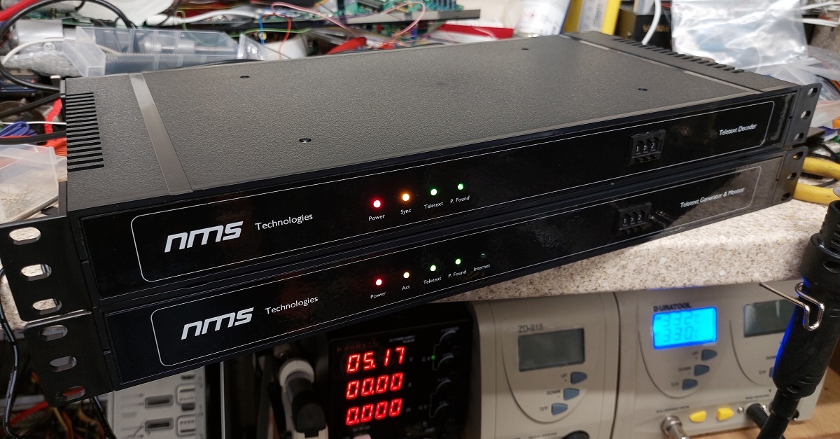
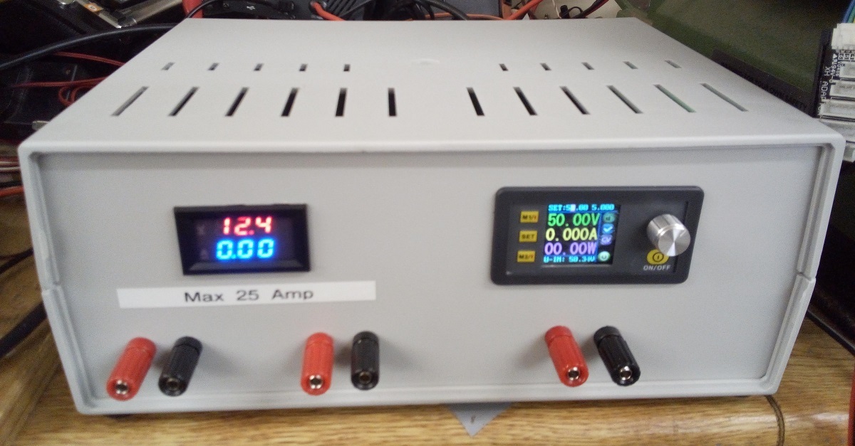
I purchased a special power supply and small lead acid battery from RS Components. The photo above shows my testing setup; The power supply handles charging the battery when there's mains power available, discharging the battery through the router when there isn't, and cutting off the output before the battery drops dangerously low.

I had to modify the power supply to lower the charging current slightly - it's expecting to charge a 7AH battery rather than my 4AH, so the current was a little bit too high for my liking. This trimpot was enough to nudge that current down a bit.

Time to mount the new power supply! First I cut out this square of vinyl to act as insulation between the power supply and the case... just in case a surge should try to jump the gap, or a bit of debris get stuck in there...

...and then securely mounted the board with four M4 stand-offs. That's going nowhere!

Here's what the final unit looks like inside. Battery is held in place with a bit of double-sided tape - and you'll see I've also added a small Arduino board to communicate the power supply's status back to the main PC.

And here's it in use in the Comms. Rack. It's been in use for just over a year now and still going strong!